Shafting
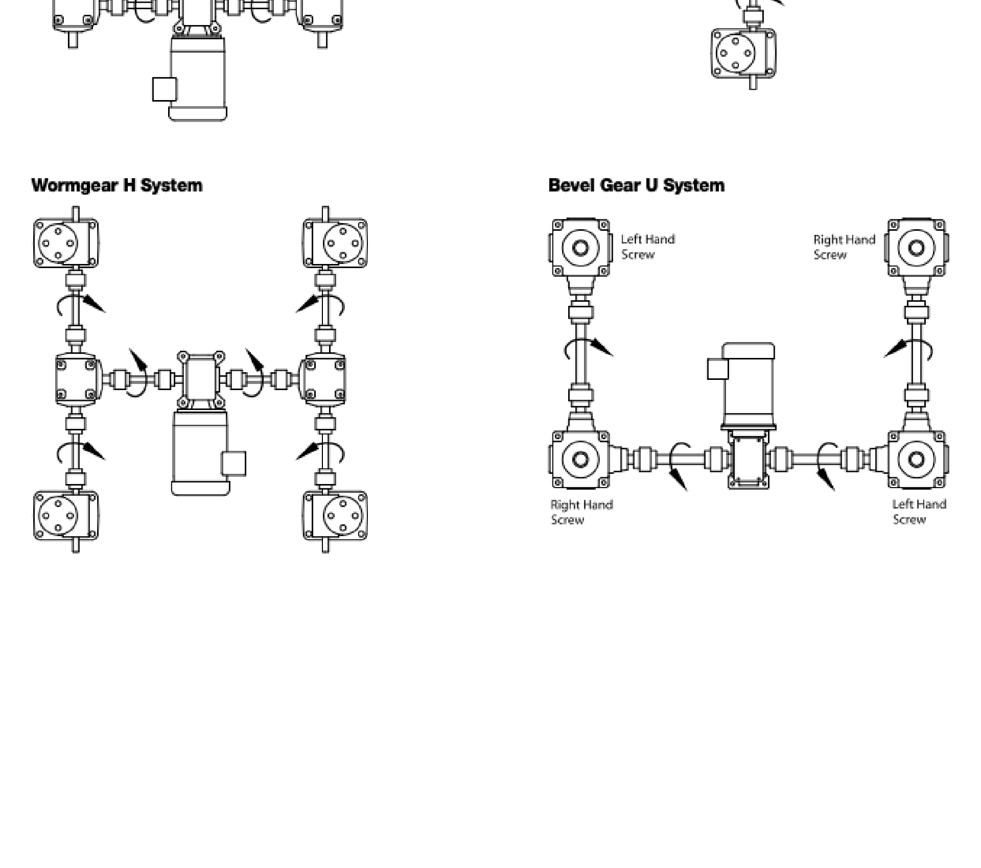
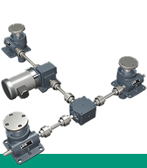
Joyce shafting matches perfectly with Joyce jacks and couplings to meet a wide variety of system requirements
Shafting
Joyce shafting matches perfectly with Joyce jacks and couplings to meet a wide variety of system requirements. Shafting is made from cold-finished 1018 steel, the ends machined to ANSI-standard keyways.
Diameter Selection Chart:
To use this chart, follow these steps:
- Find a “Shaft Torque” value in the far left column that is greater than, or equal to , you calculated torque value.
- Move to the second column to find your “Normal Shaft Diameter” (round up to arrive at an offered shaft size).
- The third column shows the maximum allowable shaft span before supports (pillow blocks) are required.
- Compare your actual shaft speed (RPM) with the maximum allowable speed ( RPM) for the shaft you have chosen. If you are above the allowable shaft speed, then increase the shaft size until it falls into the allowable range.
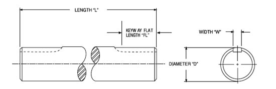
Length Specifying Information:
Joyce shafts can be ordered in 1/16 inch increments of length. When specifying shaft length, please refer to the table under Product Specifications below.
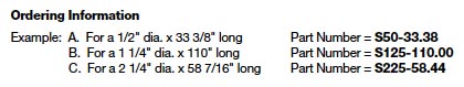
Ordering Information:
Shafting is an important component in jack and actuator systems and it is important to select the best option based on torque and rotational speed requirements. Refer to the selection chart and example part numbers included here.
Product Media
| Dimensions and Minimum Shaft Length | |||||||||||||||||||
|---|---|---|---|---|---|---|---|---|---|---|---|---|---|---|---|---|---|---|---|
| Model | S50 | S63 | S75 | S88 | S100 | S113 | S125 | S138 | S150 | S163 | S175 | S188 | S200 | S213 | S225 | S238 | S250 | S262 | |
| Minimum Shaft Length* "L" |
Flange | 7 | 7 | 7 | 7 | 7 | 7 | 7 | 7 | 7 | 7 | 7 | 8 | 8 | 10 | 10 | 10 | 10 | 10 |
| Sleeve | 5 | 5 | 5 | 5 | 5 | 6 | 6 | 6 | 7 | 7 | 7 | 8 | 8 | 10 | 10 | 10 | 10 | 10 | |
| Shaft Diameter "D" Inches | Nominal | 1/2 | 5/8 | 3/4 | 7/8 | 1 | 1 1/8 | 1 1/4 | 1 3/8 | 1 1/2 | 1 5/8 | 1 3/4 | 1 7/8 | 2 | 2 1/8 | 2 1/4 | 2 3/8 | 2 1/2 | 2 5/8 |
| Actual | .500 .498 |
.625 .623 |
.750 .748 |
.875 .873 |
1.000 .998 |
1.125 1.123 |
1.250 1.248 |
1.375 1.373 |
1.500 1.498 |
1.625 1.623 |
1.750 1.748 |
1.875 1.872 |
2.000 1.997 |
2.125 2.122 |
2.250 2.247 |
2.375 2.372 |
2.500 2.497 |
2.625 2.621 |
|
| Keyway Width "W" | 1/8 | 3/16 | 3/16 | 3/16 | 1/4 | 1/4 | 1/4 | 5/16 | 3/8 | 3/8 | 3/8 | 1/2 | 1/2 | 1/2 | 5/8 | 5/8 | 5/8 | 5/8 | |
| Keyway Flat Length "FL" | 1.25 | 1.25 | 1.25 | 1.25 | 1.25 | 1.5 | 1.5 | 1.75 | 1.75 | 1.75 | 2 | 2 | 2 | 2.5 | 2.5 | 2.5 | 2.5 | 2.5 | |
*These are the minimum shaft lengths that can be ordered when Joyce Model "S" sleeve or "F" flange-type couplings are selected.