Integrated Actuators
About Integrated Actuators
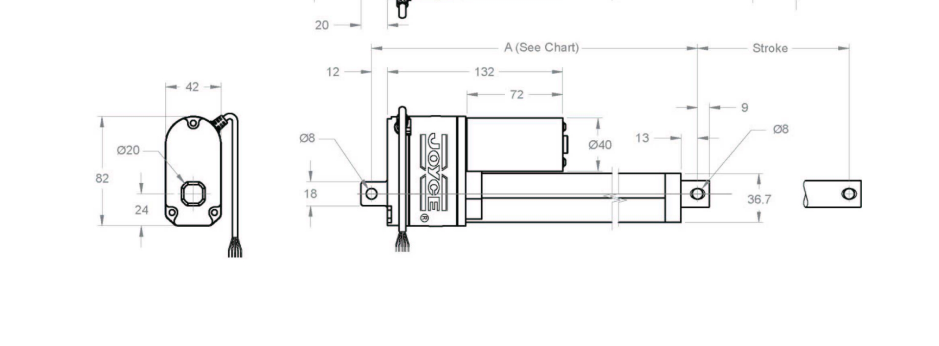
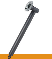
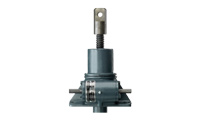
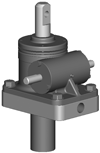
Joyce integrated actuators lift and precisely position up to one ton. Requiring only electric power, Joyce integrated linear actuators may be used in place of hydraulic cylinders, eliminating the cost and potential for leaks associated with hydraulic systems. Translating tube (TT) integrated linear actuators are well suited for use in industrial environments where protection of the lifting screw mechanism and low maintenance is desired. Traveling nut (TN) integrated linear actuators are best suited for use in environments that are relatively clean and free of dust.
- Durable aluminum housing with integral NEMA 56C-face motor flange
- Ball screw integrated actuators (BIA, HBIA) with chrome plated inner tubes
- Acme screw integrated actuators (IA, DIA) with stainless steel inner tubes
- Capable of speeds up to 345 inches per minute
- Joyce/Dayton can customize to your specifications
- Custom finishes available
Parts list and exploded views are included in the O&M Manual. Serial numbers are attached to the product housing.
Joyce offers controls for their Integrated Actuators. Contact us today!
Additional linear actuator options:
- Electric Cylinders -2.5-ton to 20-ton capacity, speeds up to 546"/min
- Multipurpose Actuators - 1600 lb. capacity, speeds up to 96"/min
- High Speed - High Precision Actuators by EDRIVE - up to 33-ton capacity, speeds up to 3900"/min, precision up to .0002"/ft.
Product Media
Available Models
Joyce offers premium finishes, outdoor paint process, and custom finishes to meet your specifications. We have a hassle-free process for delivering what you need
What you need to know to specify Integrated Actuators in industrial applications
Integrated Actuators are rated for a1-ton static thrust capacity. Selection of the best actuator for the application may require further consideration.
1. First determine the magnitude of load to be moved and the desired travel speed. Integrated Actuators are designed for most often driven by electric motors mounted directly to the NEMA 56C motor mount. Horsepower requirements are based on travels peed of dynamic load.
2. Contact a Joyce application engineer if your travel distance is greater than 24”.
3. Four Integrated actuator product variations are available.
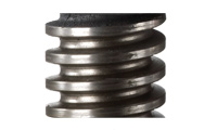
IA – features a single lead acme screw. This option is self-locking in the absence of vibration
DIA – features a double lead acme screw. Faster travel speeds, not self-locking
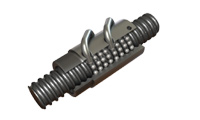
BIA – features a ball screw. Equal loads require less horsepower than acme version, requires a brake motor
HBIA – features a high-lead ball screw. Achieves fastest travel speed for product category
4 Two integrated actuator designs are available.
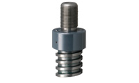
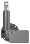
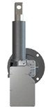
Translating tube (IA/DIA -TT or BIA/HBIA - TT) actuators are most commonly used. The load attaches to the clevis end, which extends (translates) in and out.
Traveling Nut (IA/DIA-TN, or BIA/HBIA-TN) actuators are designed with a fixed-length, rotating screw with a traveling nut. The load is attached to the traveling nut.
5. How frequently will the jack need to move the load? Integrated actuators are not designed for continuous use. Duty cycles should include a period of rest.
6. Limit switches, mounting brackets, ring encoders and special finishes are available for Integrated Actuators.
7. Standard motors have 56C frames and 230 volts, 3 phase, 60 hertz, but you may specify voltage, horsepower, and frequency needed for your application.
Where are integrated Actuators used?
Integrated Actuators are versatile and used widely throughout industry. Mount virtually any voltage, or frequency motor to the 56C motor mount. Application examples include: Gate openers, Damper adjustments, Conveyor adjustments, Platform lifts, Ergonomic lifts, Packaging equipment, Door openers.
Click To Expand

Ball Screw Options
- Right hand thread standard
- Left hand thread available on many models
- Special pitch/lead available
- Special finishes available
- Special machining options
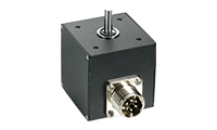
Encoders
- Standard 200 or 1024 PPR
- Quadrature wave form
- Stainless steel encoder
- Absolute encoder
- Encoders
Finishes
- Enamel finish (standard)
- Epoxy finish
- STEEL IT® epoxy
- Outdoor paint process
- Custom finishes available
- Anodized (250-lb to 1-ton)
- Nickel, Xylan®, Armoloy®
- Finishes
Follower Nuts
- For KFTN jack
- For translating jack
Limit Switches
- Rotary cam (2-4 switches)
- SPDT standard
- DPDT available
- Explosion proof available
- Limit Switches

Lubrication
- Standard grease temperature range (40°F to 220°F)
- Low temperature option
- High temperature option
- Food grade option
Machine Screws
- Right hand thread standard
- Left hand thread available on many models
- Special material available
- Special pitch/lead available
- Special finishes available
- Special machining options
- Special end conditions available
Oversized Ball Bearings
- Available for ball screw jacks
- Limits screw backlash to 0.003"
Screw Stops
- Standard on ComDRIVEs
- Adjustable
- Bolt- on
Sample Part Number:
Click on the part number to reveal additional informaton about jack designs and shaft codes.
Model Number
| Acme 1" diameter, .25" pitch |
Acme 1" diameter, .25" pitch/.50" lead |
Ball 1" diameter, .25" pitch |
Ball 1" diameter, 1.00" pitch |
|---|---|---|---|
| IA51 IA201 |
DIA51* DIA201* |
BIA51* BIA201* |
BHIA51* |
Important Note: *Integrated actuators may lower under load. Brake motors or external locking systems are recommended.
Integrated Actuator Configuration
| TT Translating Tube | TN Keyed for Traveling Nut |
Integrated Actuator Rise
Rise is travel expressed in inches and not the actual tube length.
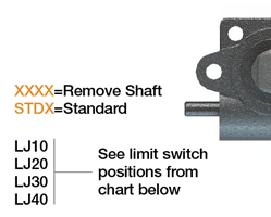
| Left Side Shaft Code | Right Side Shaft Code |
|---|---|
 |
 |
| Limit Switches | ||||
|---|---|---|---|---|
| Position | 1 | 2 | 3 | 4 |
| Left side Shaft |  |
 |
 |
 |
| Code | LJ10 | LJ20 | LJ30 | LJ40 |
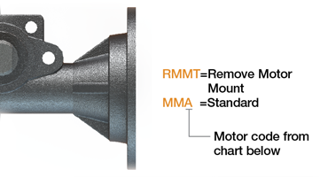
| Motors | |
|---|---|
| Size | Code |
| 1/4 HP | K |
| 1/3 HP | A |
| 1/2 HP | B |
| 3/4 HP | C |
| No Motor | X |
| Standard Motors | |||||
|---|---|---|---|---|---|
| Voltage | Speed (rpm) | 1/4 HP | 1/3 HP | 1/2 HP | 3/4 HP |
| 115/230 VAC Single Phase | 1140 | X | X | ||
| 115/230 VAC Single Phase | 1725 | X | X | X | X |
| 115/230 VAC Single Phase w/brake | 1725 | X | X | X | |
| 230/460 VAC Three Phase | 1140 | X | X | X | X |
| 230/460 VAC Three Phase | 1725 | X | X | X | X |
| 230/460 VAC Three Phase w/brake | 1725 | X | X | X | X |
| 12 VDC Permanent Magnet | 1800 | X | X | X | X |
| 24 VDC Permanent Magnet | 1800 | X | X | X | |
| 90 VDC Permanent Magnet | 1750 | X | X | X | X |
| 180 VDC Permanent Magnet | 1750 | X | X | X | X |
| Options** | |
|---|---|
| X | No additional options |
| M | Modify standard actuator |
| C12 | 12 VDC motor |
| C24 | 24 VDC motor |
| C90 | 90 VDC motor |
| C180 | 180 VDC motor |
| K | Brake motor |
| R | 1140 RPM motor |
| S | Single phase 115/230 3-ph. 60 Hz |
**Specify as many options as needed.
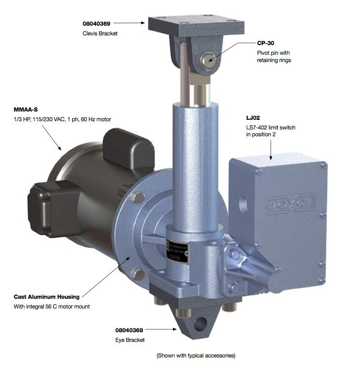
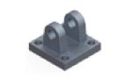
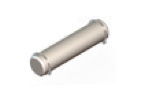
| Optional Accessories | ||
|---|---|---|
 |
 |
 |
| 08040369 | CP-30 | 08040368 |
Jack Designs
 |
 |
 |
 |
|
|
S=Translating |
K=Keyed for Non Rotation |
N=Traveling Nut |
D=Double Clevis |
R=KFTN Trunnion* |
* Standard trunnion mounts available on 2-ton through 20-ton jacks.
Metric Screw Jack Rise
Rise is travel expressed in inches and not the actual screw length.
| Model Number | BIA511 | HBIA51 | |||
| BIA201 | - | ||||
| Ball Screw | 1" diameter .250" leadball screw | 1" diameter 1.000" lead ball screw | |||
| Wormgear Ratio | 5:1 | 5:1 | |||
| 20:1 | - | ||||
| Worm Shaft Turns/1" Travel | 20 | 5 | |||
| 80 | - | ||||
| Motor RPM | 1140 | 1725 | 1140 | 1725 | |
| Lifting Speed (Inches/Minute) | 57 | 86 | 228 | 345 | |
| 14 | 21 | - | - | ||
| Rated Load (Lbs.) | 1/4 HP Motor | 925 | 625 | 225 | 100 |
| 2000 | 2000 | - | - | ||
| 1/3 HP Motor | 1225 | 825 | 300 | 200 | |
| 2000 | 2000 | - | - | ||
| 1/2 HP Motor | 1850 | 1250 | 450 | 300 | |
| 2000 | 2000 | - | - | ||
| 3/4 HP Motor | 2000 | 1875 | 700 | 450 | |
| 2000 | 2000 | - | - | ||
| Model Number | IA511 | DIA51 | |||
| IA201 | DIA2011 | ||||
| ACME Threaded Lifting Screw | 1" diameter .25"pitch | 1" diameter .25" pitch .50" lead | |||
| Wormgear Ratio | 5:1 | 5:1 | |||
| 20:1 | 20:1 | ||||
| Worm Shaft Turns/1" Travel | 20 | 10 | |||
| 80 | 40 | ||||
| Motor RPM | 1140 | 1725 | 1140 | 1725 | |
| Lifting Speed (Inches/Minute) | 57 | 86 | 114 | 172 | |
| 14 | 21 | 28 | 43 | ||
| Rated Load (Lbs.) | 1/3 HP Motor | 550 | 375 | 375 | 250 |
| 1775 | 1225 | 1250 | 850 | ||
| 1/2 HP Motor | 850 | 550 | 575 | 400 | |
| 2000 | 1850 | 1875 | 1300 | ||
| 3/4 HP Motor | 1250 | 850 | 875 | 600 | |
| 2000 | 2000 | 2000 | 1950 | ||
Lead: The distance traveled axially in one rotation of the lifting screw.
Pitch: The distance from a point on a screw thread to a corresponding point on the next thread, measured axially.
Important Note: DIA models may lower under load. Brake motors or external locking systems are recommended.