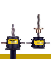
2 Ton Machine Screw Jacks
UL62, UL82, UL122
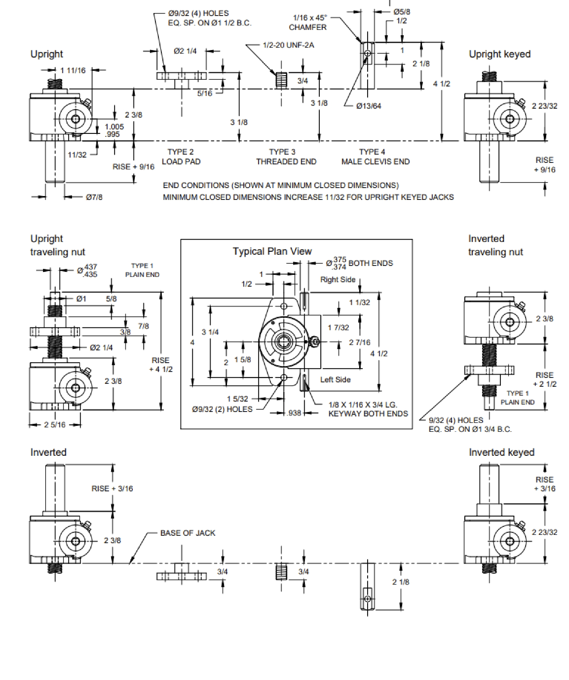
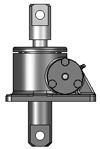
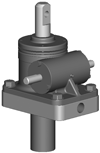
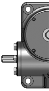
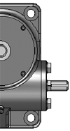
UNI-LIFT series 2 ton machine screw jacks offer precise positioning, uniform lifting speeds and capacity up to 2 Tons. Standard model configurations include upright or inverted units with translating or rotating lifting screws. End configurations include load pad, plain, threaded, and clevis ends.
Contact Joyce for 2D/3D Models:
(937) 294-6261
(800) 523-5204
2D/3D Models
Product Media
Available Models
Sample Part Number:
Click on the part number to reveal additional informaton about jack designs and shaft codes.
Model Number
| 1500 Lb | 1 Ton | 2 Ton | 5 Ton | 10 Ton | 20 Ton | 30 Ton | 50 Ton |
|---|---|---|---|---|---|---|---|
| DUL1500 | UL51 | UL62 | UL55 | UL610 | UL820 | UL930 | UL1050 |
| UL1500 | UL101 | UL82 | UL125 | UL1210 | UL1620 | UL1830 | UL2050 |
| UL122 | UL245 |
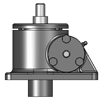
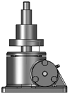
Jack Configuration
 |
 |
|
U=Upright |
I=Inverted |
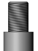
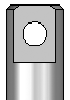
End Conditions
 |
 |
 |
 |
|
1=T1 |
2=T2 |
3=T3 |
4=T4 |
Jack Designs
 |
 |
 |
 |
|
|
S=Translating |
K=Keyed for Non Rotation |
N=Traveling Nut |
D=Double Clevis |
R=KFTN Trunnion* |
* Standard trunnion mounts available on 2-ton through 20-ton jacks.
Machine Screw Jack Rise
Rise is travel expressed in inches and not the actual screw length.
Left Side Shaft Code |
Right Side Shaft Code |
|
XXXX=Remove |
XXXX=Remove |
Optional Shaft Codes
Screw Stops and Boots
Screw stops are optional on machine screw jacks. When specified, the closed height of the jack and/or the protection tube length may be increased. When boots are added to machine screw jacks, the closed height of the jack may be increased.
Mechanical Counters
CNT0=0.001" Increments
Note: Contact Joyce/Dayton for availability and options.
Hand Wheels
HW04=4" dia
HW06=6" dia
HW08=8" dia
HW10=10" dia
HW12=12" dia
Geared Potentiometers
POTA=0-10V (IP65)
POTB=4-20MA (IP65)
POTC=0-10V w/2 switches*
POTD=4-20MA w/2 switches*
*Optional IP65 rating available
Encoders and Electronic Liit Switches
ENCX=Encoder
ELS2=2 Position Electronic Switch
ELS4=4 Position Electronic Switch
ELS6=6 Position Electronic Switch
Motor for Systems and Direct Drives
- All standard motors are 3-phase, 208-230/460 VAC or 230/460 VAC. Other motor options are available. Specify the appropriate motor size from the chart on the right.
- Refer to the "Additional Options" chart on the preceding page as needed.
- Brake motors (M2) are recommended for jacks that are not self-locking, and jacks with double lead screws.
- If the motor frequency will be varied to provide a "soft" start an inverter duty motor may be required.
Motors
| Size | Code |
|---|---|
| 1/4 HP | K |
| 1/3 HP | A |
| 1/2 HP | B |
| 3/4 HP | C |
| 1 HP | D |
| 1-1/2 HP | E |
| 2 HP | F |
| 3 HP | L |
| 5 HP | G |
| 7-1/2 HP | H |
| 10 HP | I |
| 15 HP | J |
Motor Mounts
Ordering Example:
MMA A (Motor code from chart above)
MMA=56C
MMB=140TC
MMC=180TC
MMD=210TC
Standard motor adapters are aluminum
Mechanical Limit Switches
Ordering Example:
LA (Models) 1(Number of DPDT Switches) 3(Available Positions)
| Model | Code | Available Positions | |||||||||
|---|---|---|---|---|---|---|---|---|---|---|---|
| LS7-402 | LI |
Number of DPDT Switches NOTE: Will always be 0 for LS7 models |
1 | 2* | 3 | 4 | 5 | 6* | 7 | 8 | |
| LS8-402 | LA | Left Side Shaft Options |  |
 |
 |
 |
 |
 |
 |
 |
|
| LS8-504 | LB | ||||||||||
| LS9-502 | LC | ||||||||||
| LS9-503 | LD | Right Side Shaft Options |  |
 |
 |
 |
 |
 |
 |
 |
|
| LS9-504 | LE | ||||||||||
| LS9-505 | LF | ||||||||||
| LS9-506 | LG |
*These positions are not standard. Contact Joyce/Dayton with your requirements. |
|||||||||
| LS9-507 | LH | ||||||||||
Additional Options
- X=Standard Jack, no additional options
- S=Additional Specification Required (comment as necessary)
Anti-Backlash
- A=Split Nut
- A90=A90 Design
- A95=A95 Design
Protective Boots
- B=Protective Boot
- D=Dual Protective Boot
Finishes
- F1=Do Not Paint
- F2=Epoxy Paint
- F3=Outdoor Paint Process
Motor Options
- M1=Less Motor
- M2=Brake Motor
- M3=Single Phase Motor (120VAC)
- M4=50Hz Motor
Grease/Seals
- H1=High Temperature Operation
- H2=Food Grade
Screw Stops
- ST0=Extending
- ST1=Retracting
- ST2=Both
- Specify as many options as needed
| Model | Capacity | Screw Diameter (inches) | Thread Pitch/Lead | Worm Gear Ratio | Worm Shaft Turns for 1" Travel | Tare Torque (Inch Lbs.) | Starting Torque (Inch Lbs.) | Operating Torque (Inch Lbs.) | Efficiency Rating % Approx | Screw Torque (Inch Lbs.) | Basic Jack Weight (Lbs.) | Jack Weight per Inch Travel (Lbs.) |
|---|---|---|---|---|---|---|---|---|---|---|---|---|
| DUL1500 | 1500 Pound | 0.625 | .125/.25 | 5:1 | 20 | 1 | 0.030W* | 0.022W* @500 RPM | 52.8 | 0.087W* | 2 | 0.1 |
| UL1500 | 1500 Pound | 0.625 | 0.125 | 5:1 | 40 | 2 | 0.024W* | 0.016W* @500 RPM | 37.5 | 0.065W* | 2 | 0.1 |
| UL51 | 1 Ton | 0.750 | 0.25 | 5:1 | 20 | 3 | 0.034W* | 0.023W* @500 RPM | 50.2 | 0.098W* | 9 | 0.2 |
| UL101 | 1 Ton | 0.750 | 0.25 | 10:1 | 40 | 3 | 0.021W* | 0.014W* @500 RPM | 41.1 | 0.098W* | 9 | 0.2 |
| UL62 | 2 Ton | 1.000 | 0.25 | 6:1 | 24 | 4 | 0.035W* | 0.022W* @500 RPM | 43.3 | 0.120W* | 13 | 0.4 |
| UL82 | 2 Ton | 1.000 | 0.25 | 8:1 | 32 | 4 | 0.029W* | 0.018W* @500 RPM | 40.1 | 0.120W* | 13 | 0.4 |
| UL122 | 2 Ton | 1.000 | 0.25 | 12:1 | 48 | 4 | 0.023W* | 0.014W* @500 RPM | 34.1 | 0.120W* | 13 | 0.4 |
| UL55 | 5 Ton | 1.500 | 0.333 | 5:1 | 16 | 5 | 0.052W* | 0.034W* @300 RPM | 44.7 | 0.175W* | 23 | 0.7 |
| UL125 | 5 Ton | 1.500 | 0.333 | 12:1 | 36 | 5 | 0.032W* | 0.019W* @300 RPM | 30.5 | 0.175W* | 23 | 0.7 |
| UL245 | 5 Ton | 1.500 | 0.333 | 24:1 | 72 | 5 | 0.024W* | 0.013W* @300 RPM | 15.7 | 0.175W* | 23 | 0.7 |
| UL610 | 10 Ton | 1.750 | 0.333 | 6:1 | 18 | 7 | 0.055W* | 0.035W* @200 RPM | 35.3 | 0.197W* | 47 | 0.9 |
| UL1210 | 10 Ton | 1.750 | 0.333 | 12:1 | 36 | 7 | 0.036W* | 0.021W* @200 RPM | 26.5 | 0.197W* | 47 | 0.9 |
| UL820 | 20 Ton | 2.500 | 0.500 | 8:1 | 16 | 9 | 0.060W* | 0.038W* @200 RPM | 36.4 | 0.285W* | 90 | 1.8 |
| UL1620 | 20 Ton | 2.500 | 0.500 | 16:1 | 32 | 9 | 0.039W* | 0.023W* @200 RPM | 27.4 | 0.285W* | 90 | 1.8 |
| UL930 | 30 Ton | 2.750 | 0.5 | 9:1 | 18 | 10 | 0.057W* | 0.035W* @200 RPM | 34.4 | 0.307W* | 103 | 2.1 |
| UL1830 | 30 Ton | 2.750 | 0.5 | 18:1 | 36 | 10 | 0.037W* | 0.022W* @200 RPM | 25.8 | 0.307W* | 103 | 2.1 |
| UL1050 | 50 Ton | 4.250 | 0.667 | 10:1 | 15 | 12 | 0.076W* | 0.046W* @150 RPM | 31.4 | 0.463W* | 230 | 5 |
| UL2050 | 50 Ton | 4.250 | 0.667 | 20:1 | 30 | 12 | 0.049W* | 0.029W* @150 RPM | 23.5 | 0.463W* | 230 | 5 |