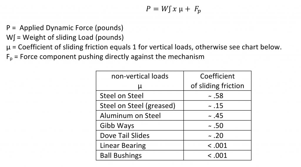
A comprehensive load calculation that accounts for multiple force components. Included in these components are: weight of the sliding mechanism (vertical), weight of the sliding mechanism multiplied by the coefficient of sliding friction (horizontal), direct forces resisting the linear motion (i.e. cutting tools), other applicable force components.
A load that is parallel to the centerline of the screw shaft and equally distributed around the mounting surface. It is the recommended methodof attaching the load to the the ball nut.
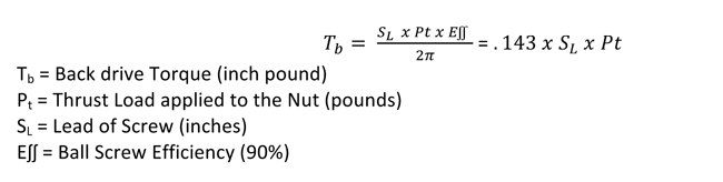
The torque produced through the screw shaft by a thrust load on the ball nut. Ball screws can coast or back drive due to the high efficiency of the mechanism (90%). If back-driving is not acceptable, a method to resist the overturning back-driving systemic torque, such as a brake, will be required to hold the load. If back-driving is desired, the lead of the screw should be at least 1/3 of the screw diameter. Ideally the lead should be equal to the screw diameter. This calculated torque is the minimum amount of braking torque to hold the load in position.
The axial free motion between the nut and the screw. It determines the amount of lost motion between the nut and screw on a horizontal application. The backlash on ball nuts ranges from .005" to .015", depending on the screw size.
(Ball Circle Diameter) The theoretical cylinder passing through the center of the balls bearings when they are in contact with the ball screw and ball nut races.
A black oxide finish is provided on ball screws to help prevent corrosion during shipping and brief storage. Long-term corrosion resistance is accomplished by the rust inhibiting properties of the screw lubricant. In applications with extreme environments, additional coatings such as nickel, hard chrome, zinc or other coatings can be applied. Contact Joyce/Dayton for detailed specifications.
(Life Expectancy) This is the total accumulated inches of travel, under constant load, of a clean and properly lubricated screw and nut before first evidence of fatigue develops. It is expressed in inches of travel. Ball screw life is rated similarly to ball bearing life - in terms of 1,000,000 inches of travel under stated and rated loads.
This is the ability of the screw shaft to withstand compressive forces without buckling. The fundamental limit occurs when the compressive load exceeds the elastic stability of the screw shaft, resulting in bending and buckling of the screw. This mode of failure can only occur when the screw shaft is in compression. Joyce/Dayton recommends limiting the maximum compressive load to 80% of the calculated column load strength.
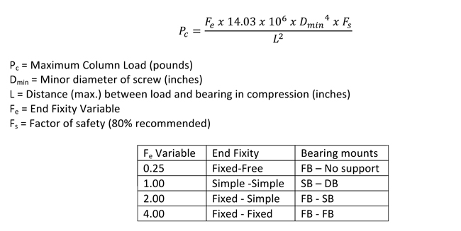
This is a load that tends to compress the screw or buckle the screw shaft. Consideration must be given to column load limitations when screws are used in compression.
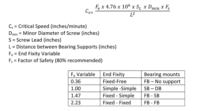
This is the theoretical linear velocity (inches/minute) which excites the natural frequency of the screw. As the speed of the screw approaches the natural frequency (critical speed), the screw shaft begins to resonate. This resonance occurs whether the screw or the nut rotates and regardless of the screw orientation. Joyce recommends limiting the maximum linear velocity to 80% of the calculated critical speed value.
This is the number of inches the ball screw will travel over a given number of years of service.

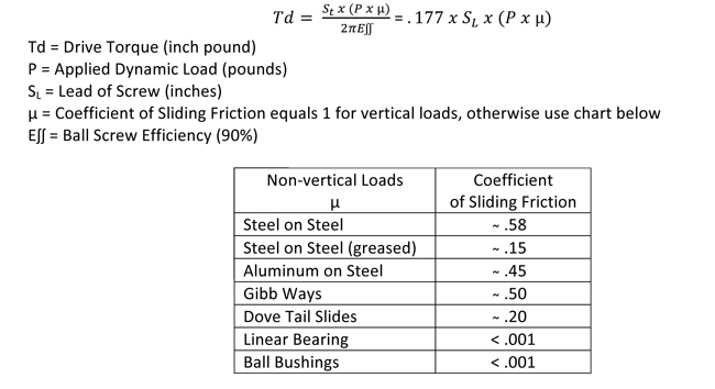
The amount of torque required by the ball screw to move the load. This torque does not take into account any inertial loading required for acceleration.
This is the maximum thrust load under which the ball screw assembly will achieve a minimum of 1,000,000 inches of travel before first signs of fatigue are present.
(Moment Load) This is a load that tends to rotate around the screw imposing a non-axial load on the screw and nut assembly. Eccentric loads reduce the rated life of ball screws and nuts. They are not recommended.
(Moment Load) This is a load that tends to rotate around the screw imposing a non-axial load on the screw and nut assembly. Eccentric loads reduce the rated life of ball screws and nuts. They are not recommended.
This is the ability of a ball screw to convert torque to thrust, expressed as a percentage. Ball screws are typically 90% efficient.
(Bearing mount support configuration) This refers to the method by which the ends of the screws are supported. The end fixity describes the bearing configuration being used to support the rotational axis of the screw. End fixity combinations are determined as a result of critical speed, column loading, and system stiffness calculations. Fixed-Fixed supports provide the greatest support and Fixed-Free supports provide the least support.
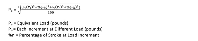
This is a calculated load value used for applications in which the load is not constant throughout the entire stroke of travel. Use the maximum load value when sizing drive components for systems.
The axial distance the screw or nut travels in one revolution.
(Accuracy) The difference between the actual distance traveled and the theoretical distance traveled based on the lead of the screw. The lead error for a standard screw will not exceed +/- .007 inches per foot. Lead error is cumulative based on the actual length of the ball screw thread.
Use this formula when evaluating loads other than the rated load of the ball screw and ball nut. It is based on the inverse cube ratio. When operating at ½ the rated load, life will be increased to 8 times standard life. When operating at twice the rated load, life will be reduced to 1/8 of the standard life.
(Rated Load/Actual Load)3 x 106 = life of assembly under actual load
Lubrication is required to achieve optimum life for a ball screw assembly. Ball screws that are not lubricated can experience up to 90% reduction in calculated life. In general, standard lubrication practices for anti-friction rolling element bearings apply. Grease, oil, or dry film lubrication can be used. Many ball nuts are equipped with 1/8-27NPT lube ports machined into the nut body.
Proper lubrication of ball screw assemblies is critical to maintaining optimum efficiency and life. It is most ideal to introduce the lubricant directly into the ball nut. Lubrication ports can be found in various locations on the ball nut or flange, depending on the specific product. A 1/8-27 NPT lubrication port is located on most ball nuts, but some units have a lubrication port located on the flange, or in the external threads of the ball nut. A Zerk fitting is available on the outside of a few ball nuts.
Joyce/Dayton offers full service machining capabilities to supply screw assemblies that are ready for installation. We offer standard end machining that can accommodate our line of bearing blocks as well as custom machining to meet your specific mounting requirements. Screws can also be supplied cut to length with no machining.
The outside diameter of the screw thread.
(Synchronous Screws) Used when multiple screws are being driven by a single drive in order to keep the screws synchronized. To minimize operational misalignments, lead errors are matched at the factory.
Most ball screws and nuts are made from alloy steel and case hardened to Rc 56 (minimum).
(Root Diameter) The diameter of the screw shaft as measured at the bottom of the ball thread track. This diameter is used in column load and critical speed calculations. Minor diameter is also a consideration in support bearing selection.
The distance from one thread on a screw to a corresponding point on the next thread parallel to the screw axis. Pitch and lead are equal on single start screws.
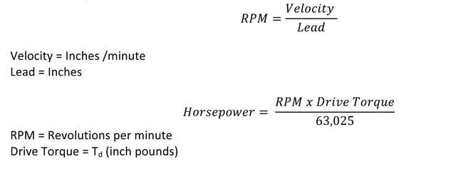
The power to drive a ball screw assembly is a function of the required drive torque and motor R.P.M. Horsepower should be calculated based on the maximum torque required during stroke or cycle. The highest torque requirements generally occur during acceleration, due to inertial loading.
The additional torque required to overcome the frictional components of the preload force. This additional torque needs to be added to the drive torque in order to calculate the required torque for constant velocity.
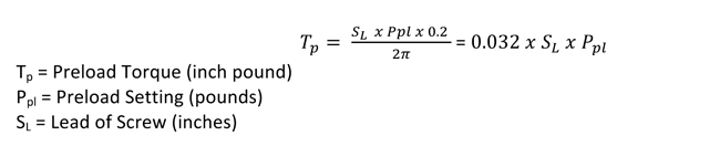
A method of eliminating backlash in a ball screw assembly. This is accomplished by the use of one group of ball grooves in opposition to another. Preloading increases stiffness (resistance to deflection) and provides for accurate positioning with very little increase in applied torque or load capability.
This is a coiled spring that conform to the ball screw thread. It is installed in the inactive part of the ball nut. The spring is inactive during normal operation and it does not contact the screw, however, in the rare event that the balls are lost from the ball nut, the safety spring assumes the load and prevents the nut from “free falling” down the screw. The spring is not designed to maintain normal operation and the ball screw should be taken out of service after the first engagement of the safety spring. Safety springs are available for all ball screws, but they are not mandatory unless the screw is being used to lift, support, or otherwise transport people. Please contact Joyce/Dayton with your specific requirements
The number of independent threads on the screw shaft. The lead on the screw is calculated by dividing the threads per inch by the number of starts.
This is extremely important in minimizing screw vibration. Our ball screw stock is straight to 0.010 inches per foot. Not to exceed .025 inches over the entire length.
The process of selecting a unique ball bearing size for reducing backlash to as little as .001 inches.
(Radial Load) A load that is applied perpendicular to the screw shaft. This type of load will also reduce the rated life of the ball screw and nut assembly.
This is the maximum non-operating load capacity above which permanent damage of the ball track occurs.
This is a load that tends to stretch that ball screw. It is the preferred mode of attaching the load because it eliminates column loading as a limiting factor on the screw.
Wiper kits are available for all standard ball screw models. The nylon brush wiper is designed to keep large particles from entering the ball nut, however, for harsh environments, bellows boots are also recommended.
Wiper kits for larger ball nuts, 1 1/2" diameter and larger are mounted internally. These wiper kits include 2 wipers and 2 snap rings. When wipers are specified a groove for the retaining ring is machined into the internal diameter of the ball nut to accomocate the assembly of the wiper into the ball nut.
Wipers kits for smaller ball nuts are assembled to the external surface of the ball nut. These kits include (1) cap for the back of the ball nut, and (2) bristle wipers, one for each end. There are several possible methods of attaching these to the ball nut depending on the customer's mounting configuration. Contact sales@joycedayton for additional information.