Ball Screw ComDRIVEs
About Ball Screw ComDRIVEs
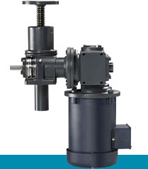
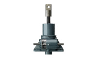
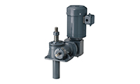
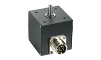
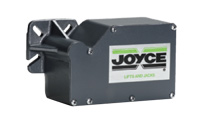
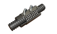
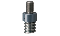
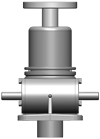
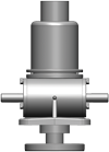
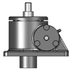
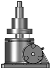
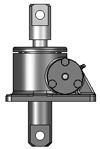
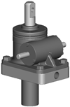
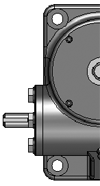
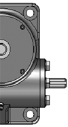
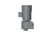
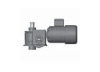
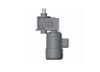
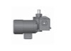
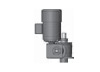
Joyce Ball Screw ComDRIVEs combine a ball screw jack, motor and gear reducer into a single compact unit. Motorized ComDRIVEs are available in 2-ton through 30-ton capacities. Available in Translating, KFTN, and double clevis designs, they provide travel speeds up to 55.5 inches per minute. Ball screw ComDRIVES require up to two-thirds less input torque to move the load than a similarly sized machine screw jack ComDrive. They require a brake motor or external locking device to hold position.
- Ball screw ComDRIVES are available in a variety of ratios and screw leads
- They can power an entire jacking system
- Reduce the number of components that must be specified
- Simplify designs
- Reduce installation costs with only a single plate needed to mount the Reduce the number of couplings and shafts required in multi-jack systems
- 230/460 volt, 3-phase, 60 hertz motor is standard
- Custom finishes available
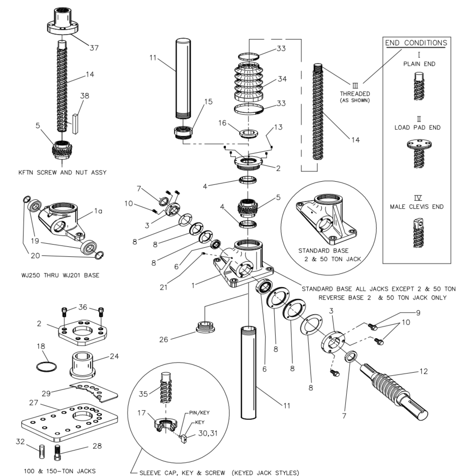
Parts list and exploded views are included in the O&M Manual. Serial numbers are attached to the product housing.
Product Media
Available Models
Joyce/Dayton provides motor controls ranging from simple Motor Starters to complex positioning systems and Custom controls. Every system that is powered by an electric motor requires a control system. At Joyce, we know that choosing the best option can sometimes be a challenge. That’s why our Engineers are available to help you through the process.
Boots and special finishes are available for Joyce Ball Screw Jacks. Choose from a variety of boot materials and designs for the jacks you select(translating or KFTN). Joyce offers premium finishes, outdoor paint process, and custom finishes to meet your specifications. We have a hassle-free process for delivering what you need.
What you need to know to specify Motorized Ball Screw ComDRIVE jacks in industrial application.
Travel speeds and load capacities of standard ComDRIVE jacks are listed in the catalog. Here are a few tips.
- Select the best option from the chart based on your load and speed.
- Remember the charted load is based on a single ComDRIVE. If you pair a ComDRIVE with a jack, choose a motor that can lift the total system load.
- High-lead ComDrives can achieve faster travel speeds than their standard-lead counterparts. High-lead part numbers begin with "H" (HWB62, HWB245, etc.).
- Standard ComDRIVES use 1750 RPM, 3 phase, 60 HZ motors but we can supply whatever you need.
- Brake motors are needed to hold position.
- When you buy a ComDRIVE with a companipon jack, Joyce will deliver a matched jack(s) with the same closed height.
- Larger capacity ComDRIVES are available upon request. Let us know what you need.
Ball Screw Jacks are rated based on their static thrust capacity from 1-ton to 50-tons. But the selection of the best jack for the application requires further consideration.
- When jacks are loaded in compression one must consider the load carrying capacity of the lifting screw (column load). How high do you need to lift the load? Choose a jack whose lifting screw is stout enough to handle the load at full rise.
- Consider the travel speed of the DYNAMIC load. The speed at which the load will be moved is a limiting factor. How fast do you need to move the load? Sometimes high lead ball screw jacks or bevel ball actuators are a better choice in a given application.
- How frequently will the jack need to move the load? Ball screw jacks are much more efficient than machine screw jacks, so heat is less of a factor in their operation, yet cycles for ball screw jacks must include some periods of rest.
- You can choose a ball screw jack that meets specific life requirements. A calculated ball nut life (in inches) can be established for ball screw jacks based on the load, and duty cycle. Use the JAX® Online software to determine this.
Once loads, duty cycles, and travel speeds are established, designers must select which jack design to use.
- Translating Design Jacks are most often selected. With this design, a driven input worm acts on an internal worm gear causing the lifting screw to extend or retract. Operation requires that rotation of the lifting screw be prevented. This rotation it restrained whenever two or more jacks are tied to the same load.
- Ball screw jacks cannot be keyed for non-rotation the same way that machine screw jacks are keyed. Contact Joyce for a design solution if you need a keyed ball screw jack.
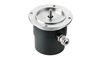
- Keyed for Traveling Nut Design (KFTN) jacks are another option. These jacks have a fixed length lifting screw that rotates. Loads are attached to a flanged “traveling” ball nut that translates up and down the length of the rotating screw. This type of jack is ideal for applications that cannot accommodate a screw protection tube or that require a flush mount
Special features inherent in wormgear ball screw jacks.
Ball screw jacks include ball nuts that are about 90% efficient so the jacks require much less energy to lift an equal load than their machine screw jack counterpart. They are NOT self-locking so a brake motor needs to be included in the drive system and hand wheels are not a recommended option.
Take the work out of using screw jacks in systems
Tell us what you need or use our exclusive JAX® Online software (it’s free). We will put together complete systems with single or multiple screw jacks for you. The software is great because it calculates motor horsepower and shaft diameters and torques. There are several common arrangements, but the program is flexible and allows you to design what you need..
Where are worm gear ball screw jacks used?
Motorized worm gear ball screw jacks are fast and efficient. They can accurately position and hold loads up to 50-tons. Examples include: Platform lifts, Damper adjustments, Ergonomic lifts, Maintenance lifts, Roll adjustments, Earth Station Antennas, Solar Trackers, Conveyor adjustments, Packaging equipment, and Gate adjustments.
Ball Screw Options
- Right hand thread standard
- Left hand thread available on many models
- Special pitch/lead available
- Special finishes available
- Special machining options
ComDRIVE Options
- Special reducer ratios available
- Special mounting positions available
- Special motor adapters available
- Mount limit switch to gear reducers
Encoders
- Standard 200 or 1024 PPR
- Quadrature wave form
- Stainless steel encoder
- Absolute encoder
- Encoders
Finishes
- Enamel finish (standard)
- Epoxy finish
- STEEL IT® epoxy
- Outdoor paint process
- Custom finishes available
- Anodized (250-lb to 1-ton)
- Nickel, Xylan®, Armoloy®
- Finishes
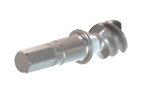
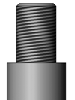
Input Shaft (worm)
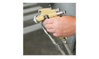
- Square or hex to fit tool
- Special lengths
- 17-4 stainless steel available
- Metric diameters available
- One side can be cut off
- Other modifications available
- Input shaft cover available
Limit Switches
- Rotary cam (2-4 switches)
- SPDT standard
- DPDT available
- Explosion proof available
- Limit Switches

Lubrication
- Standard grease temperature range (40°F to 220°F)
- Low temperature option
- High temperature option
- Food grade option
Oversized Ball Bearings
- Available for ball screw jacks
- Limits screw backlash to 0.003"
Potentiometers
- 0-10V (POTA)
- 4-20mA (POTB)
- 0-10V with limit switches (POTC)
- 4-20mA with limit switches(POTD)
- IP65
- Potentiometers
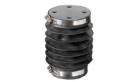
Protective Boots
- Protection from dirt and dust
- Guard against moisture
- Guard against corrosive contaminants
- Neoprene coated nylon (std)
- Special materials available
- Boot Material Chart
- Protective Boots
Screw Stops
- Standard on ComDRIVEs
- Adjustable
- Bolt- on
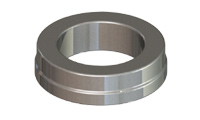
Thrust Rings
- Used in applications where static loads exceed jack capacity
Sample Part Number:
Click on the part number to reveal additional informaton about jack designs and shaft codes.
Model Number
| 2- Ton Standard | 5- Ton Standard | 10- Ton Standard | 10- Ton Heavy Duty | 20- Ton Standard | 30- Ton Standard |
|---|---|---|---|---|---|
| CDB62 CDB122 CDB242 |
CDB65 CDB125 CDB245 |
CDBL810 CDBL2410 |
CDB820 CDB2420 |
CDB820 CDB2420 |
CDB1130 CDB3230 |
| 2- Ton High Lead | 5- ton High Lead | 10- Ton Standard High Lead | 10-Ton Haavy Duty High Lead | ||
| CDHB62 CDHB122 CDHB242 |
CDHB65 CDHB125 CDHB245 |
CDHBL810 CDHBL2410 |
CDHBL810 CDHBL2410 |
Important Note: *Not self-locking, may lower under load. Brake motors or external locking systems are recommended.
H: High lead (2-ton, 5-ton and 10 ton only).
(For 25:1 ratio, contact Joyce/Dayton.)
Jack Configuration
 |
 |
|
U=Upright |
I=Inverted |
End Conditions
 |
 |
 |
 |
|
1=T1 |
2=T2 |
3=T3 |
4=T4 |
Jack Designs
 |
 |
 |
 |
|
|
S=Translating |
K=Keyed for Non Rotation |
N=Traveling Nut |
D=Double Clevis |
R=KFTN Trunnion* |
* Standard trunnion mounts available on 2-ton through 20-ton jacks.
Ball Screw ComDRIVE® Rise
Rise is travel expressed in inches and not the actual screw length.
Left Side Shaft Code |
Right Side Shaft Code |
|
XXXX=Remove |
XXXX=Remove |
Optional Shaft Codes
Screw Stops and Boots
Extending screw stops are standard on ball screw ComDRIVEs and they are not adjustable. When boots are added to ball screw ComDRIVEs, the closed height of the jack may be increased.
Geared Potentiometers
POTA=0-10V (IP65)
POTB=4-20MA (IP65)
POTC=0-10V w/2 switches*
POTD=4-20MA w/2 switches*
*Optional IP65 rating available
Encoders and Electronic Limit Switches
ENCX=Encoder
ELS2=2 Position Electronic Switch
ELS4=4 Position Electronic Switch
ELS6=6 Position Electronic Switch
ComDRIVE Reducers
Ordering Example:
P2 (Mounting Positions) A (Ratio) C (Motor code from chart above)
| Mounting Positions | ||||
|---|---|---|---|---|
| Code | P1 | P2 | P3 | P4 |
| Left Side Shaft Options |
 |
 |
 |
 |
| Right Side Shaft Options |
 |
|
|
|
| Ratio |
|---|
| 5:1 Code A |
| 7.5:1 Code B |
| 10:1 Code C |
| Motors | |
|---|---|
| Size | Code |
| 1/4 HP | K |
| 1/3 HP | A |
| 1/2 HP | B |
| 3/4 HP | C |
| 1 HP | D |
| 1-1/2 HP | E |
| 2 HP | F |
| 3 HP | L |
| 5 HP | G |
| 7-1/2 HP | H |
| 10 HP | I |
| 15 HP | J |
All standard motors are 3-phase, 208-230/460 VAC or 230/460 VAC. Other motor options are available including international voltages, and single phase AC. Specify the appropriate motor size from the chart above. Refer to the “Additional Options” chart on the preceding page as needed. Brake motors are required for ball screw ComDRIVEs®. Contact Joyce/Dayton for other options.
Mechanical Limit Switches
Ordering Example:
LA (Models) 1(Number of DPDT Switches) 3(Available Positions)
| Model | Code | Available Positions | |||||||||
|---|---|---|---|---|---|---|---|---|---|---|---|
| LS7-402 | LI |
Number of DPDT Switches NOTE: Will always be 0 for LS7 models |
1 | 2* | 3 | 4 | 5 | 6* | 7 | 8 | |
| LS8-402 | LA | Left Side Shaft Options |  |
 |
 |
 |
 |
 |
 |
 |
|
| LS8-504 | LB | ||||||||||
| LS9-502 | LC | ||||||||||
| LS9-503 | LD | Right Side Shaft Options |  |
 |
 |
 |
 |
 |
 |
 |
|
| LS9-504 | LE | ||||||||||
| LS9-505 | LF | ||||||||||
| LS9-506 | LG |
*These positions are not standard. Contact Joyce/Dayton with your requirements. |
|||||||||
| LS9-507 | LH | ||||||||||
Additional Options
- X=Standard Jack, no additional options
- S=Additional Specification Required (comment as necessary)
Anti-Backlash
- A=Split Nut
- A90=A90 Design
- A95=A95 Design
Protective Boots
- B=Protective Boot
- D=Dual Protective Boot
Finishes
- F1=Do Not Paint
- F2=Epoxy Paint
- F3=Outdoor Paint Process
Motor Options
- M1=Less Motor
- M2=Brake Motor
- M3=Single Phase Motor (120VAC)
- M4=50Hz Motor
Grease/Seals
- H1=High Temperature Operation
- H2=Food Grade
Screw Stops
- ST0=Extending
- ST1=Retracting
- ST2=Both
- Specify as many options as needed
| 2 Ton Model Number | CDB62 | CDB122 | CDB242 | CDHB62 | CDHB122 | CDHB242 | ||||||||||
|---|---|---|---|---|---|---|---|---|---|---|---|---|---|---|---|---|
| Reducer Ratio | 5 | 7 1/2 | 10 | 5 | 7 1/2 | 5 | 7 1/2 | 10 | 5 | 7 1/2 | 10 | 7 1/2 | 5 | 7 1/2 | 10 | |
| Travel Speed IPM | 13.88 | 9.50 | 7.04 | 6.94 | 4.75 | 3.47 | 2.38 | 1.76 | 55.50 | 38.00 | 28.16 | 19.00 | 13.88 | 9.50 | 7.04 | |
| Lifting Capacity (Lbs.) |
1/3 HP | 4,000 | 4,000 | 4,000 | 4,000 | 4,000 | 4,000 | 4,000 | 4,000 | 1,025 | 1,455 | 1,925 | 2,595 | 3,015 | 4,000 | 4,000 |
| 1/2 HP | 1,580 | 2,220 | 2,925 | 3,955 | 4,000 | |||||||||||
| 3/4 HP | 2,400 | 3,375 | 4,000 | |||||||||||||
| 5 Ton Model Number | CDB65 | CDB125 | CD245 | CDHB65 | CDHB125 | CDHB245 | |||
|---|---|---|---|---|---|---|---|---|---|
| Reducer Ratio | 5 | 10 | 10 | 10 | 5 | 10 | 10 | 10 | |
| Travel Speed IPM | 26.29 | 13.34 | 6.67 | 3.34 | 55.50 | 28.16 | 14.08 | 7.04 | |
| Lifting Capacity, Lbs. |
1 HP | 6,770 | 10,000 | 10,000 | 10,000 | 3,200 | 5,950 | 10,000 | 10,000 |
| 1 1/2 HP | 10,000 | 4,900 | |||||||
| 2 HP | 6,600 | ||||||||
| 10 Ton Model Number | CDBL810 | CDBL2410 | CDHBL810 | CDHBL2410 | |||||
|---|---|---|---|---|---|---|---|---|---|
| Reducer Ratio | 5 | 10 | 5 | 10 | 5 | 10 | 5 | 10 | |
| Travel Speed IPM | 19.72 | 10.00 | 6.57 | 3.34 | 41.63 | 21.13 | 13.88 | 7.04 | |
| Lifting Capacity, Lbs. |
1 HP | 8,555 | 16,425 | 20,000 | 20,000 | 4,050 | 7,780 | 9,910 | 18,445 |
| 1 1/2 HP | 13,390 | 6,340 | 15,500 | ||||||
| 2 HP | 18,210 | 8,625 | 20,000 | ||||||
| 3 HP | 20,000 | 20,000 | 13,370 | 20,000 | |||||
| 5 HP | 20,000 | ||||||||
| 10 Ton Model Number | CDB810 | CDB2410 | CDHB810 | CDHB2410 | |||||
|---|---|---|---|---|---|---|---|---|---|
| Reducer Ratio | 5 | 10 | 5 | 10 | 5 | 10 | 5 | 10 | |
| Travel Speed IPM | 20.81 | 10.56 | 6.94 | 3.52 | 41.63 | 21.13 | 13.88 | 7.04 | |
| Lifting Capacity, Lbs. |
1 HP | 8,100 | 15,560 | 19,820 | 20,000 | 4,050 | 7,780 | 9,910 | 18,445 |
| 1 ½ HP | 12,685 | 20,000 | 6,340 | 15,500 | |||||
| 2 HP | 17,255 | 8,625 | 20,000 | ||||||
| 3 HP | 20,000 | 20,000 | 13,370 | 20,000 | |||||
| 5 HP | 20,000 | ||||||||
| 20 Ton Model Number | CDB820 | CDB2420 | |||
|---|---|---|---|---|---|
| Reducer Ratio | 5 | 10 | 5 | 10 | |
| Travel Speed IPM | 20.81 | 10.56 | 6.94 | 3.52 | |
| Lifting Capacity, Lbs. |
1 HP | 6,965 | 14,285 | 16,720 | 33,120 |
| 1 ½ HP | 11,480 | 27,550 | |||
| 2 HP | 15,980 | 38,360 | |||
| 3 HP | 25,330 | 40,000 | 40,000 | 40,000 | |
| 5 HP | 40,000 | ||||
| 30 Ton Model Number | CDB1130 | CDB3230 | |||
|---|---|---|---|---|---|
| Reducer Ratio | 5 | 10 | 5 | 10 | |
| Travel Speed IPM | 20.60 | 10.46 | 6.87 | 3.49 | |
| Lifting Capacity, Lbs. |
3 HP | 24,295 | 46,080 | 54,745 | 60,000 |
| 5 HP | 42,165 | 60,000 | 60,000 | ||
| 7 ½ HP | 60,000 | ||||
Important Note: Ball Screw ComDRIVEs are not self-locking. Brake motors or external locking systems are required.